Tags
Arduino, Furnace, Heating, Noritz, PEX, Radiant Floor, Radiantec, renovations, Water Heater
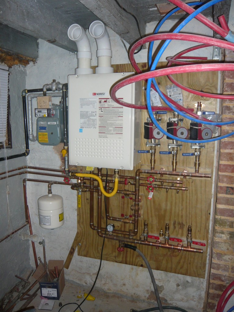
I’ve finally gotten enough done on our core plumbing that I’m willing to post a photo. This has been my baby for a few months and I’m obsessed with every detail. As with most of the other projects, we’re aiming to save as much space as possible. We have reduced our entire heating, hot water, gas and water distribution systems from a furnace, water heater, ducting, and associated plumbing into a 4′ wide x 5′ tall x 1′ deep corner. This transforms a basement only fit for storage into one fit for a workshop. We’ve gained a full floor on our house.
Here is how the system works:
Water enters from the city via a 3/4″ copper pipe (lower left) through a code required back-flow preventer and expansion tank into our 1″ radiant floor manifold. From there 3 pumps send water to each of our 3 floors (once we hook up the PEX you see in the top right), back to the lower manifold, through the tankless [high-efficiency condensing] water heater, through a 1 way valve and back around again.
This design uses manifolds made by Radiantec and is laid out based on their reference design. I’ve made a few slight changes to save space, but keep everything oriented as they suggest. They key was layering everything in planes. I planned this out in Sketchup which really helped to visualize different layouts before I even had the parts in hand.
We get hot water out of the system for the house from just after the water heater and before the heating circuit’s one way valve. Hot water that is removed is replaced by water from the water main. Cold water for the house comes from different parts of the system depending on the position of a manual diverter valve. When we are heating the floors, the valve pulls cold water from the main before it gets to the heating circuit. When we are not heating the floors, cold water has to go through all of the floors before being taken out before the water heater. In addition to preventing stagnation during the summer, this is supposed to supplement our cooling by removing a few BTUs of heat via the floors as we use water. Summer heat literally goes down the drain. The downside of this is that our “cold” water will now be room temperature. Since I dont like drinking warm water, we’re going to tap into the main just after the back-flow preventer for nice cold drinking water which we will run through filter to remove the city water taste.
Due to the efficiency of the water heater and its low exhaust gas temperatures we are able to use PVC pipe for the intake and exhaust (top). This is going to be run across the ceiling and out the side wall into the alley. The run is short enough and has so few bends that we can get away with running 3″ PVC.
The electricity has not yet been run around the basement. We will need around 1 amp for each pump and an amp for the water heater itself. We’ve decided to try and build our own thermostat based on an Arduino microcontroller. Input will be temperature sensors in the floors of each room (Dallas DS18B20) and output will be solid state relays which can supply up to 2 amps per circuit. I’ve come up with a simple algorithm that turns the pumps on if the temperature is below a set point (and off when they reach the set point + hysteresis). The hard part is the interface. We have an Arduino Ethernet shield which allows us to connect to the controller via our network (and the Internet). I’m hoping to make apps for our phones that allow us to set the temperature and check the status of the house from anywhere with a wifi connection. Data logging is also a goal. This is going to take a little while to implement so for now we’ll set the temperature with a laptop via USB.


